
|
| | . |
| Return to the schoolhouse | Download in Microsoft Word Format | ||
|
by
the Southern California Traction Club
November
15, 2003 1.
BACKGROUND
The purpose of this lesson is to provide background prototype
information in support of the lessons on the installation of ORR HO scale
Street Railway Track. Since for all practical purposes traditional street
railway track has virtually disappeared from most of North America, it is
necessary to review some of the peculiarities that were encountered in the
development and installation of track in city streets before trying to
replicate this in models. In modeling, we are restricted by many factors
so compromises have to be made. Trolleyville feels that modelers should be
aware of the prototype in order to make the best modeling compromises and
decisions. 2.
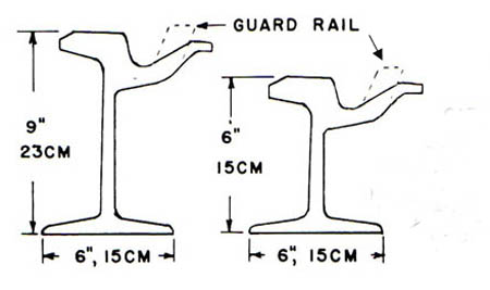
PROTOTYPE GIRDER RAIL
Prototype Girder rail, two examples of which are shown below, is
different from the 'T' rail commonly used in railroads and was invented to
eliminate damage to wheels from street paving materials such as
cobblestones, Belgian block, concrete, macadam and asphalt. The rail
contained an integral flangeway and also served as an I-beam that did not
flex under the weight of the streetcars and cause damage to the adjacent
pavement. Such rail is still available in Europe as tram rail. Girder rail
was extremely durable, lasting in many grade crossings in Southern
California almost 30 years past the departure of the Pacific Electric. The
guardrail, when added, formed a type of rail that we will call girder
"High Guard" rail. This
“High Guard” rail is normally used for curves, at crossings and at
turnouts. Richard Orr gave the HO scale modeler a relatively easy
opportunity to model girder rail installations with the track he developed
in the 1980s. This track is now available from Custom Traxx (www.customtraxx.com).
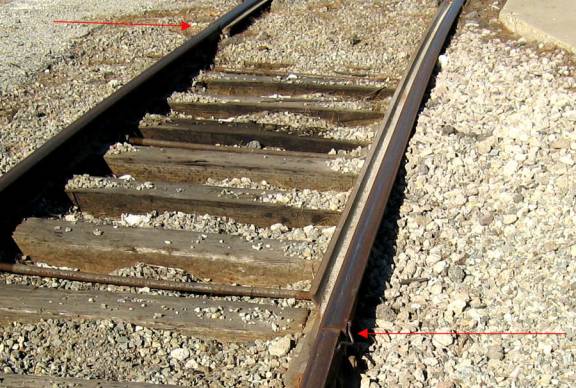
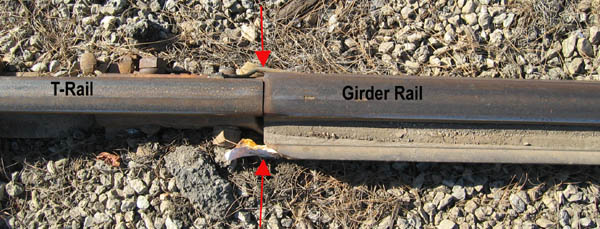
Some
photos of Girder Rail compared to T-Rail are shown below. The next photos
were taken in Hawthorne, October 2003.
3.
OGIVE SHAPED CURVES Many
prototype curves, especially the sharp curves found in east coast city
streets where streets were narrow, were not of uniform radius as is
commonly the case of the "snap" track that is originally used by
all modelers. These curves tended to be ogive shaped with the smallest
radius in the center and easements at the ends. This helped the clearance
situation in tight places and eased the car into the curve with a more
gradual motion. Streetcars
tended to have tapered ends to minimize clearance problems with other cars
at these curves. In this lesson, we will begin by installing constant
radius curves. But there will be at least one ogive curve installed.
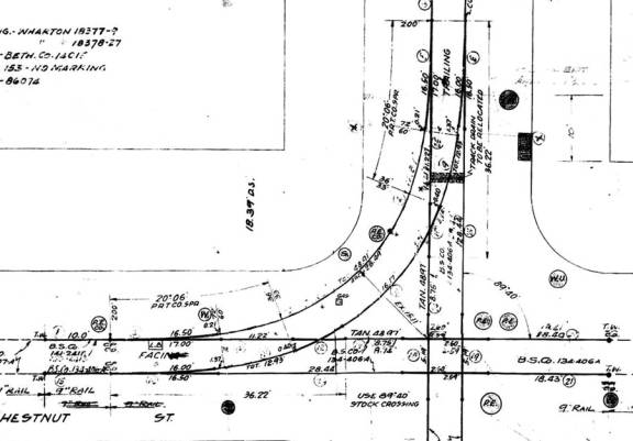
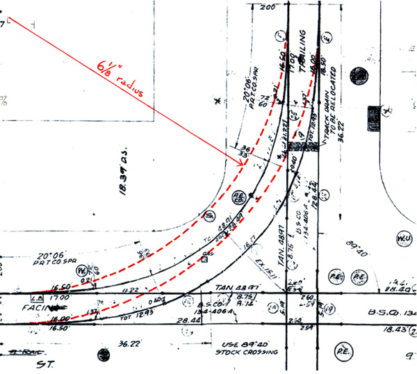
Directly below is a Philadelphia Rapid Transit track diagram for the
intersection of 9th and Chestnut that we obtained from Charles
Long, an avid traction modeler who is a long time member of the East Penn
Traction Club. This clearly shows the ogive shape of the curve.
During
this investigation into streetcar curves, we discovered that most of the
streets in center city Philadelphia were not laid out at exactly right
angles. Note on the above drawing that the crossing angle is 89 degrees,
40 minutes. We understand this problem was corrected by the time that
streets in North and West Philadelphia were laid out. But, note the
variance in the radii of the curve. The points start at 200 ft radius (27
inch radius in HO scale) and graduate down to 72' radius (10
inch radius in HO scale), then the curve goes to 60 ft radius (8
inch radius in HO scale) and then
to 36 ft (5 inch radius in HO scale).
The middle one-third of the curve is 33' radius (4.5-inch
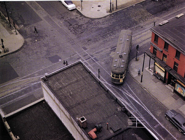
radius in HO scale). The photograph below, courtesy of an Ed Miller
photograph, shows a similar curve at 15th and Arch in 1954.
Notice the gradual, almost straight portion of the curve at the
switchpoints. Also notice how close the car is to the curb as it turns.
Without the ogive shaped curve, the center of the car would have struck
people standing on the curb waiting to cross the street.
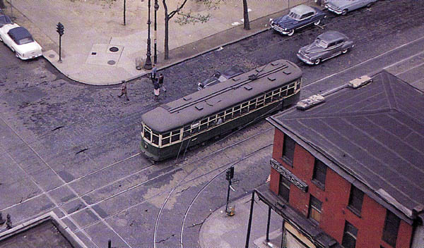
The
next view shows the portion of the curve that is under the car in the
above photo. The car in the above photo is an unmodernized 8000 series
Peter Witt taking a short turn on Route 48. The car would have normally
turned left and proceeded eastbound to Front & Arch. The car in the
photo below is another unmodernized 8000 series Peter Witt car eastbound
on either route 9 or 33.
4
"DEVIL" STRIPS
The
space between double tracks was popularly called a "devil" strip
since there was very little room between passing cars in some cases. Many
an accident would occur there if you were in the wrong place at the wrong
time. Note how narrow the "devil strip" was on Arch St. in the
above photo. Keep in mind that Philadelphia track gauge is 62 1/4"
and the cars were no more than 100" wide.
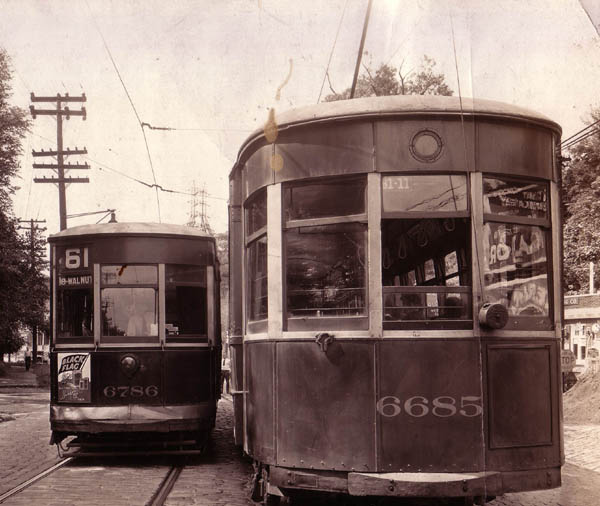
The next photo was taken on August 18, 1933 as a result of an
accident. It was used to demonstrate that there was only 5.0 inches
clearance between passing streetcars on Ridge Avenue at School Lane. This
is the main reason for bars and/or grates on the sides of the cars. Both
cars in the photo are the famous Philadelphia Nearside cars, of which
there were 1500 at one time.
Of
course there were wider devil strips, especially in cities that used
"boulevard poles" between such double tracks to support the
overhead wire, as is currently the case on St. Charles Avenue in New
Orleans. Incidentally, route 61 was converted to trackless trolleys and
continued in that fashion until the 1960's. 5.
MODELING OGIVE CURVES
Returning
to our plan of 9th and Chestnut (below) and superimposing a 6
1/8" radius curve (red dashed lines)
on the plan, the tracks are really close to the curb and any car using
that curve could strike a lot of people on the sidewalk. The city fathers
and anyone on that street corner would not have liked that track location
at all. The use of the ogive curve moved the track five feet farther from
the curb. Note illustration below:
Using
ORR turnouts and girdle rail with 6 1/8" radius curves (44.4
ft radius) would result in the track shown in red. Detail on
construction of this type of curve is contained in Parts 2 and 3 of the
ORR TRACK lessons. 6.
"NON-CLEARANCE" CURVES Many
prototype double track curves in city streets were
"non-clearance" curves. This means that two streetcars could not
pass on these curves without hitting each other. In some cases, this must
be the case in modeling, but should be avoided as much as possible,
especially on club layouts were inattention could cause a model to be
seriously damaged. In most of these cases, when the tracks were originally
installed, short four-wheel cars were used which could pass each other.
When the double track cars came, the problem existed and they were slowly
eliminated as track replacement occurred. Such activity happened again as
recently as the 1980s when Philadelphia replaced PCC cars with the longer
Kawasaki LRTs. 7.
MODELING LIMITATION IN HO SCALE Currently
in HO scale, standards permit much larger flanges than prototype so girder
rail flangeways are larger. This forces switchpoints to be larger and some
track plans will be dramatically affected. Keep this is mind, especially
in areas where multiple turnouts will be located close together.
For many reasons, most likely unavailability, street car systems remaining in service in North America are using plain T-rail for street track. The area around the track is paved with concrete and the flangeway is formed in such concrete. In October 2010, the trackwork in the entire intersection at 30th & Church in San Francisco was replaced over a three-day period and captured on film. 9.
FOR MORE INFORMATION
If
you really desire to model street railways, check other lessons in the
Trolleyville Schoolhouse, especially the ORR TRACK lessons or visit the
EAST Penn Traction Club web site at www.eastpenn.org.
You can email us at orrtrack@customtraxx.com
with any questions. When asking questions about proposed track plans,
please provide all data, especially a scale drawing of the proposed plan,
so that we can answer your questions as accurately as possible. If you
live in Southern California, contact the Southern California Traction Club
at sctc@customtraxx.com.
The club conducts many workshops on this and other traction related
subjects at local Great American Train Shows. |