|
 | . |
|
Return to the schoolhouse | Download in Microsoft Word Format |
||
|
|
|
|
|
|
|
|
|
|
|
|
|
|
|
|
|
|
|
|
|
|
|
|
|
|
|
|
|
|
|
|
|
|
|
|
|
|
|
|
|
|
|
|
|
|
|
|
|
|
|
|
|
|
|
|
|
|
|
|
|
|
|
|
|
|
|
|
|
|
|
|
|
|
|
|
|
|
|
|
|
|
|
|
|
Building a
Curved Crossing on a Traction Layout (A simple way that works)
by George
Huckaby
April 15, 2004
1. BACKGROUND
The Southern
California Traction Club started using their car storage and display modules in
2003 after thefts of brass equipment occurred at an east coast traction show.
These display modules are located within the rectangular display so the public
can see the cars but not have access to them.
Upon using the display, it was found that the entry track to the yard
worked very well and should be matched by a similar outbound track.
The original
inbound track was created using an Atlas Code 83 #542 turnout mated to a
section of #532 18" radius curved track. The crossing had been
"grafted" into the section of curved track and was done while the
module was under construction. This time the crossing would have to be
fabricated off module and then "grafted" into existing trackage.
Although this method would not probably be used by a Master Model Railroader,
the use of curved and straight snap track with the rails already held firmly in
the straight or curved position aids in keeping the correct track gauge,
throughout this process.
Since this
track will be used on a traction layout with operable overhead wire, insulating
the two rails is not a factor, simplifying the entire construction and
installation process.
This is not
the only way to build a curved crossing, just a method that we have used twice,
found that it works and yielded track that did not turn out to be
derailment-prone in either case.
2. INITIAL PREPARATION STEPS
We will be
using the same Clover House 266 printed circuit ties that we have used for the
ORR Street Trackage in another lesson. These printed circuit ties are
.056" in thickness while the Atlas plastic ties are .078". So a strip
of Evergreen StripStyrene #8210 .022" X .112 will be affixed under each
printed circuit tie. This crossing is to be fabricated "off-module"
so a piece of plywood, on which to fabricate the crossing, was needed. A nearby
construction project yielded a brand new section of 15" by 23"
1/2" plywood and the project was underway.
1. Since the
module tracks are on two-inch centers, mark two parallel lines on the plywood,
two inches apart and then draw an 18" radius curve tangent to the outer
line.
2. Take the
#542 turnout and attach the section of #532 curved track to the diverging route
and lay out the track along the lines and using T-pins (called wing pins in
some circles) fasten the track along the lines to ensure a correct fit.
3. While the
track is in place, scribe a line along the edge of the ties to mark the tie
edges on both the straight and curved tracks. These lines will be used to
measure the correct length for ties under the crossing itself. This will also
mask the difference between the plastic ties and the printed circuit ties.
4. Solder the
rail joiners between the turnout and the piece of curved snap track while the
two pieces of track are "pinned" in place.
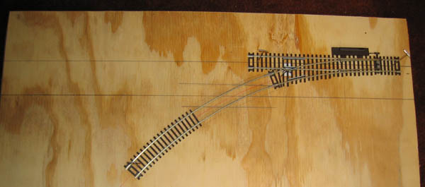
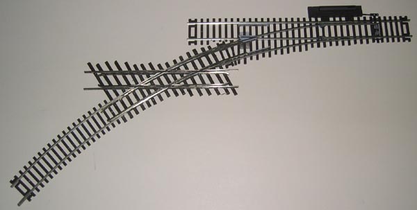
5. Remove the
pins and before moving the trackage, note how many ties need to be removed.
Turn the track upside down and carefully remove the plastic ties along the
curved track section where the crossing will intersect the curved track and
then reattach to the plywood using the same pin points. Shown below is the
project at this step.
3. INSTALLING THE
CURVED PORTION OF THE CROSSING
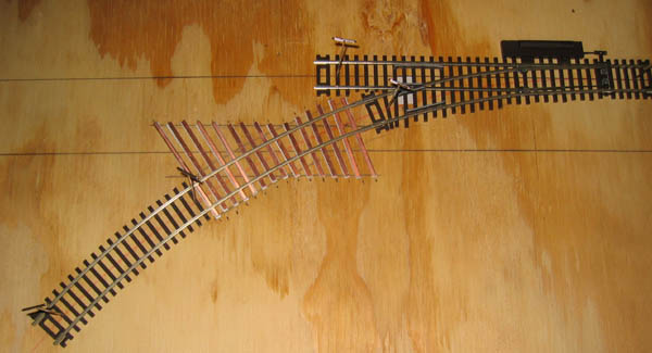
a. Carefully
begin to cut the printed circuit ties to fit between those tie lines that you
scribed earlier. They will all be different sizes so each must be measured
carefully. After the tie is and cut for the particular location in the
crossing, use a sanding stick or sandpaper and rough the bottom side of the
tie. Using ACC (We
recommend the use of the CA4000 Light Cyanoacrylate Adhesive Delivery System.
This ACC comes in a syringe type dispenser and
we end up using the entire amount before discarding the tube. This
systems is available from Dental Ventures of America, Corona, CA 800-228-6696), affix a piece of #126 StripStyrene to
the bottom of the tie and using a small amount of rubber cement or Hob-E-Tac on
the styrene, place the tie in place. Keep repeating this step until all ties
are in place as shown in the next photo.
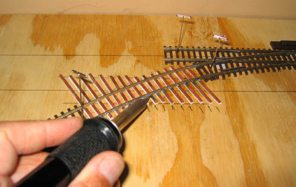
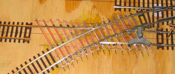
b. Once the
ties are completed and are fixed in position, solder the inner rail to the ties
from the outside only. We do not want solder on the inside of the rail as the
guardrails will be placed there and we do no want these rails any higher than
the running rails. This operation is being shown below.
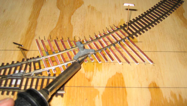
c. Use a track
gauge when soldering the outer rail, again from the outside only. There will be
a flange guard rail adjacent to this rail also. Do not perform these soldering
steps too quickly. Allow time for heat to dissipate between each tie soldering
step or heat will expand the ties and when they subsequently cool, the track
will be slightly narrow in gauge. Note the track gauge in the photo below.
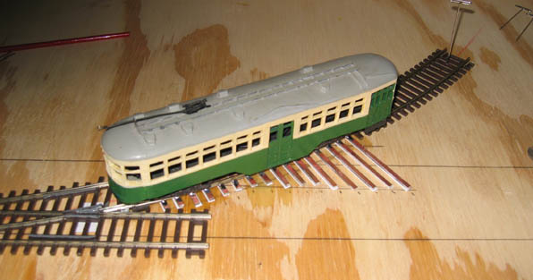
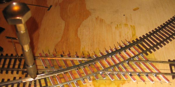
d. The photo
below shows a test car over the new trackage.
4.
INSTALLING THE STRAIGHT PORTION OF THE
CROSSING
The next steps
involve installing the straight track portion of the crossing. This involves
placing the track in the correct position to ensure a straight crossing in line
with the rest of the straight track, installing the track to the curved track,
installing the curved flange guardrails and fitting the remaining running rails
and straight flange guard rails.
a. Position
some straight sections along the scriber line from the ends of the printed
circuit ties. Ensure that the tracks are along the same line and that when the
rails are extended through the crossing the track will be perfectly straight.
Measurement and eyes help here a lot. Carefully check the next two photographs:
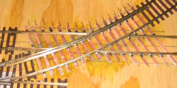
b. This is the
step where four lengths of rail are prepared to fit between the curved portion
of the crossing and the straight tracks. Extreme amounts of filing will be
required to get a good fit at the curved track. Take care and be patient. Start
with a length of rail 1/4" longer than required. File, measure and check
with the 'good old' eye test prior to installing. This is NOT the time to be in
a hurry. Be patient and file and fit carefully. Install a rail joiner on the
fixed straight track and when the final fit is made, the rail can be
temporarily spiked to the plywood and when the position is correct, solder the
rails to the ties from the outside. Two of the four rails to be fit have been
installed in the next photo:
Do the same thing with the remaining
two rails except add one important step. Use a track gauge as shown below to
insure the correct track gauge with the already installed rail. This is
important to avoid painful derailments later when the crossing is installed.
c. The next
item will be to install the flange guard rails through the crossing. The general rule in fabricating crossed
crossings in to complete the curved rails first and then fit the straight
pieces in. Since these rails will be fit
web-to-web to the running rails, this is the reasons why we recommended
soldering the running rails from the outside. This will help ensure that these
flange guard rails are not higher than the running rails. To give a natural
look to this flange guard rail in a traction environment, the flange guard rail
will extend all the way to the frog guard rails in the turnout. So prior to
installing the flange guard rail, we clipped the flared portions from the
plastic guard rails and will but our new flange guard rail up to it. The
flange guard rail will extend from these plastic rails through the crossing to
just past the end of the printed circuits ties.
1) Carefully trim the flared ends
from the frog guard rails and carefully measure the length of rail needed.
2) Place the rail adjacent to the
inner rail of the curve from the frog guard rail to the desired end. When the
correct length is made, flare the end of the guard rail and install at first by
temporarily spiking in place to the plywood base. Note both notes below and
when the flange guard rail is determined to be the correct position, solder in
place.
Note: If the
rail joiner between the turnout and the curved snap track prevents the rail
from being placed close to the running rail, use a Dremel tool and grind some
of the web from the guard rail in the area of the rail joiner.
Note: Where
the flange guard rail is over plastic ties, the molded spikes may also prevent
the guard rail web from being close enough to the running rail. Use a soldering
iron and heat the guard rail slightly and push the guard rail toward the
running rail. Then using a 68 drill, drill holes in the ties for later spiking
to the base after the turnout and crossing combination is installed in the
final location.
Using the same
methodology, installed the opposite running rail flange guard rail. The
crossing now looks as shown below:
d. There are
only four more pieces of rail to be installed to complete this crossing, two
running rails and two flange guard rails for the straight track crossing. These
cuts and files must be exact and fit snugly between the flange guard rails
already Installed. Be very patient. Start with a longer piece of rail than
necessary and file down to fit. The flange guard rails should be carefully
soldered together at the joint and filed to make them prototypically correct.
e. Make one
last check of all the soldered joints
between the rails and the ties to ensure that all the joints are secure.
f. Check track
gauge on both the straight and curved portions of the crossing and correct and
discrepancies by heating joints and carefully moving the rails.
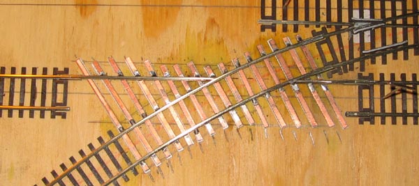
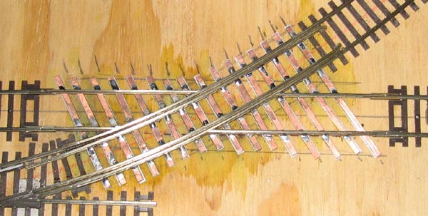
g. Prior to
removing the crossing and turnout combination from the plywood is to paint the
printed circuit ties using Floquil Rail Brown 110070 or Floquil Railroad Tie
Brown 110014 and the results are shown below:
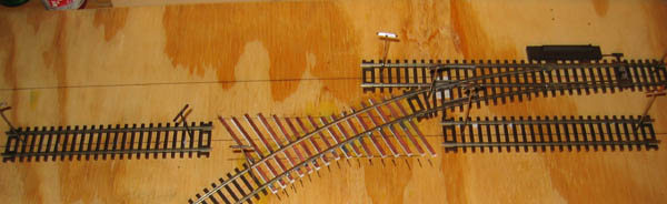
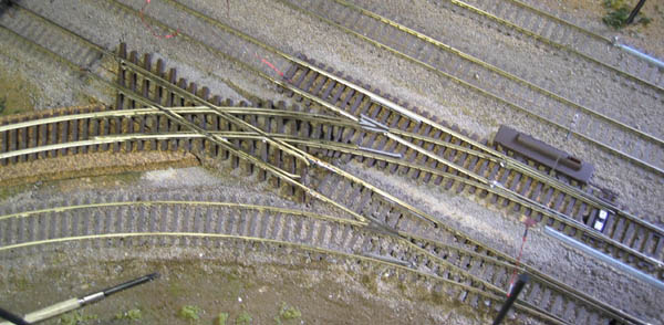
5. INSTALLATION
ON THE MODULE a.
The combination crossing turnout combination is shown in the just after
installation on SCTC module 969. More ties will be installed along with ballast
and the installation will be complete.
6. FOR MORE
INFORMATION
If you have any questions on this
article, please do not hesitate to contact Trolleyville. If you desire to model
street railways, review other lessons in the Trolleyville Schoolhouse and visit
the EAST Penn Traction Club web site at
www.eastpenn.org.
You can email us at
orrtrack@customtraxx.com
with any questions. When asking questions about proposed track plans, please
provide all data, especially a scale drawing of the proposed plan, so that we
can answer your questions as accurately as possible.
Happy Trolley Modeling!
|