Hartland "Sparky" Locomotive
Kit-Bash Project - Part One
September
30, 2003
Karl
Johnson
This is Part 1, of a 2 part series
to kit-bash a small electric locomotive. It involves the use of drills, paints,
small metal, wood and plastic parts, knives, pliers. Best of all, you will bring your own imagination and creativity
to the table.
BACKGROUND
Hartland Locomotive Works produces
(…what appears to me to be…) a nice, easy model to kit bash. In the reviews I
have read (mainly Garden Railways) they state in the review that the locomotive
is of no particular prototype and measures out to 1:24th (1/2”) scale. I have obtained and run mine, and it is a
"good runner", as I call them.
So modifying the motor and gear train is one big item you’ll not need to
worry about.
In my own measurements, this may
work out to be 1:24th scale, but there is lots of room for making
this into a more realistic looking electric locomotive, again with no
particular prototype in mind. In my experiences of looking at many pictures of
single truck engines that have been either produced by a large manufacturer
(GE, Westinghouse, etc.); home-built in the shops by the railroad itself or
created from some other piece of equipment, there is not a lot of commonality
to these creations.
Personally, I like the Westinghouse
small 45 – 60-ton engines, even though they are double truck engines, and this
is a single truck model. That is the
basis for this particular Kit-Bash.
PROCEDURE
One thing that strikes me on the
Hartland car, is the roof, or ceiling height. On the model as produced, it is
about 6 feet from floor to ceiling.
Again, I am not saying that this height is incorrect, I just believe
that the model would “look” better with a higher ceiling. Maybe your railway or railroad has some
clearance issues, and the model ceiling height could be an issue. Take some
time to check these facts out to assure your new creation fits into your
exiting clearances. Nothing worse than
a nice model, venturing out on it’s first run, crossing paths with some
obstacle that would ruin some or all of your work.
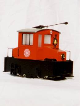
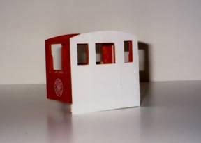
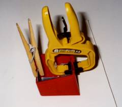
So, assuming you have your Hartland
“Sparky" as shown below or South Shore Line engine, lets start to work.
The first process is to take the engine apart. You should have a simple Philips
screwdriver, another slotted screwdriver and a receptacle for the parts
storage. Remove the trolley pole or
pantograph. The car that I was using was equipped with a trolley pole and
required the Philips to remove the screw attaching it to the car. Set the pole
and screw into the storage receptacle.
Turn the engine over; there is a
clamp affair that holds the motor truck onto the body. Take the slotted
screwdriver and pry one end, a twist motion (between the engine block and
clamp) to ease the clamp out beyond the end of the tab. Once it is free, do the same at the other
end. The motor block should come out and the “light pole” with it. Twisting the
clamp might take you a moment to get it worked over the tabs. Set the motor block aside.
There are two Phillips screws under
the floor area, remove these and the cab should come of the base or frame. Set
the cab aside. Remove the hoods from
each end (lift up by the cab end and they should come off easily). Turn the
frame over; remove the handrails and the 1/2 round air tank (I think that is what these are!), on each
end by squeezing the tabs. Set these
parts aside. The frame should be clear of all items.
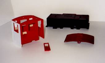
The cab, remove the windows,
headlight lenses, roof. Set the
headlight lens and the windows aside.
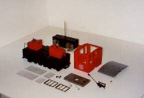
At this point, as shown above, the
car shell, frame roof should be stripped of all the parts. Now, wasn’t that
fun! You still have all your fingers,
etc…!
Now the challenge is about to
begin!
1. Some materials you need to have
to complete this project are; Styrene sheets (Evergreen sheet styrene, .010
thickness), various wood strips,
plastic angle pieces, etc
2. I had already decided to add to
the ceiling/roof height by 1 scale foot, and to add some rivet detail to this
model. Some considerations you might want to think about, headlights, do you
keep the ones on the model, or add new ones, window glazing, etc… I chose to add rivets, add new headlights,
and add my own window details.
To do this, I would use the styrene sheets to create a new
side skin or sheets to the entire cab.
3. Beginning with the Cab, very
carefully, I cut off the headlight barrels from the cab ends and sanded them
somewhat smooth. I cut off the small piece under the side cab windows to make
this smooth. You want the sides of the cab to be fairly smooth so when you glue
on the styrene sheets, they attach with out too many big bumps that will show
later on. If you model is a “show room”
piece, that just arrived from the factory, you’ll want this area very smooth.
If it is a working model, the engine during it’s life on your “railway”
probably had some beating over the years and this, not being quite so prefect,
will add some “texture” to it.
4. I also choose to make the front,
lower window heights all the same. Taking some wood I filled in the lower
portions of the front drivers window + the door window. You can see how this
will eventually look in the next photo
5. If you want to add to the floor
to ceiling height, now is the time! Taking your styrene sheet, measure up a
1/2” (= 1 scale foot). Draw a new line that you will now use to line up the
lower edge of the cab. Line up the
lower part of the cab trace out each side and front panel. Use a good sharp
pencil to out line the cab, window detail.
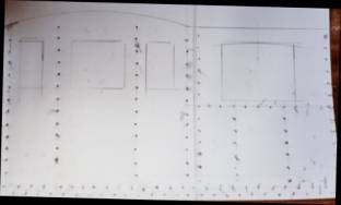
6. If you want to add rivet detail,
this is also now the time. Draw some
straight parallel lines about a scale 3 and 6 scale inches up from the lower
edge of the styrene> A few equally spaced lines vertically, about 3 scale inches
from the side edge, maybe one down the middle, and across under the window.
7. Now, using your ruler, mark off
spacing, about every 6-scale inches were the rivet would be. Again be careful when doing this, as this is
what people (including you) will later see.
8. There are many ways to create
rivet details. I use a small center punch and a very small brass hammer, and
lay underneath the styrene a small piece of soft plywood. Placing the center
punch on the line and space marked off, and a very slight blow of the hammer,
you are knocking in the rivet detail.
NOTE: You may want to practice a bit of scrap styrene materials to
perfect your technique!
9. After knocking in all the rivet
detail, check the “exterior” and see how it looks, did you miss any, some more
needed in some areas, Did I rivet across the lower doors areas where I should
not have?
10. Very carefully, using a metal
straightedge and knife cut the four walls apart. Leave some extra material at
the top edge. This will be trimmed later after gluing. Carefully fit the sheets to each wall, do
they line up OK, windows (Not yet cut out) look OK, rivet details is in the
right places? Now cut some small wooden
strips, which will act as the lower parts of the cab wall where there is now no
material other that the styrene. When I measured the amount of wooden spacer or
filler needed, I left a little edge of the styrene hanging lower then the new
wooden filler piece and this will be used as a part of the flooring later on.
See next photo.
11. Another thing I decided on was
I wanted a door to “open” and so I very carefully cut out one door, and made
this an open door way as shown in the previous photo. Set the door aside, use
some styrene and wood to increase the door height, as we will add this on
later.
12. So, if things look OK, smear on
some glue onto one cab side, and lay on the styrene materials, clamp or add
weights to insure a good strong bond between the cab and the styrene. Let this sit over night at least (or say
10-12 hours). I wanted the styrene to be well bonded to the body before I moved
on. Glue all four sides, and add the lower wood fill part. Make sure this
wooden piece is parallel with the car sides.
13. After the glue is dry,
carefully start to cut out the window areas. I also started to prime and paint
the styrene as I went along.
14. For the “hoods” I carefully cut
length wise, and added some heavy plastic pieces to the insides, so that the
hoods would be wider. After they were carefully glued together, I added some
filler wooden pieces for strength and then carefully added some styrene (with
rivet detail) over the top and front side. Again leaving some extra materials
to be rimmed off later
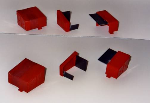
The next photo shows the hoods
being clamped together to make the wider hood.
15. For the roof, I filled in with
wood and modeling filler to make the roof skin smooth, and added some to the
inside ceiling to make this smoother. I
cut small pieces of wood for trolley cleats and also cut some trolley boards to
length. I made these so they will extend over the cab roof ends about 3/4”
(18”scale inches). I started to paint the roof a reddish color, along with the
boards.
16. For the frame, I cut off the
rounded extension between the two-journal boxes at the lower edge of the frame
to make this part straight (on each side)
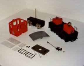
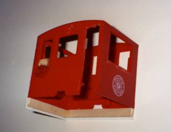
17. The next photo shows the cab,
cab door, main frame, roof. You can see the cleats I have sanded to fit the
roof contour and glued in place.
In Part 2, we will finish the cab, roof, and frame. We will
add the trolley pole and base, trolley pole hooks, Kadee couplers, interior
details, and paint and finish the model.
About
the author!
Karl Johnson was raised in central
upper Massachusetts were the local Bus Company still used “Street Railway” in
it’s name. So, yes, he rode the street
railway line each day to and from school, but they had advanced (?) to using
new modern GM busses. There were remains here and there of the old railway
line; i.e., a crossing with the Boston & Maine on River Street, or an old
piece of rail showing through the blacktop out on Summer street. He was once
watching the street repair guys pulling out some old step type rail from an
intersection, when they offered to bring it to his house. Since our house and
yard was at the top of a twenty plus flight of stairs, I could not see where I
would have put that track!
There was also an old New Haven
branch that went trough the local towns. After moving from one city to the
next, he was able to ride the local switcher during his summer days off from
school. It also allowed time to play with model trains at home and on summer
vacations to go to the Seashore Trolley Museum, where his father volunteered as
a motorman, and, of course, he helped to change the poles at the ends of the
line. For a while, he was even a ride
operator at a local amusement park.
Eventually, he found himself
volunteering in the museums shop area, working on track, and learning about and
helping to move these crippled old cars with no motors, just set onto trucks
around the museum. During the summers, he got himself employed by the museum,
first as a ticket agent and car barn “host”, and then later in the shop
restoring streetcars, running maintenance on the small fleet of cars operated
for the public, and learning how to operate the various machines the museum
had. After graduation from High School,
he spent much of his employment time not only at the museum, but also a local
eatery, a construction company, etc.
One fall, Karl decided to take off
and head west to get out of the snows of Maine. He left in mid January, delayed
a day due to yet another snowstorm. He found himself as a volunteer at a local
streetcar museum, and later in the year found employment at a real transit
company that still maintained a good size fleet of PCC cars, and a small assortment
of work and excursion cars.
As his employment continued working
for the transit company, working various shifts, he began working on the latest
modern equipment, only to be dragged away to work on a small Summer “historic”
car operation, that would operate down one of the busiest main streets in
America.
Many years later, Karl worked on a
cable rope system and assisted in the rebuild specification for the overhaul of
a small flock of PCC cars. He even traveled to Italy to look at yet another
group of 1928 built cars and as this lesson is written still enjoying his
employment with the Transit Company.
In 2000, he started to collaborate
with a gentleman in the United Kingdom who was producing 1:24th
scale traction parts, and attempted to help him sell these items here in the
US. As a result of that experience, I could see that there is a small market
for G scale traction items, which could be sold here in the US. More
manufacturers are bringing out traction items (Hartland, LGB will have a New
Orleans car along with it’s European trams). Light Rail Products was created to
fill in the vacuum, creating detail parts for traction buffs everywhere. Please
see our web site, both here at Trolleyville and at www.lightrailproducts.com