
|
|
| . |
| Return to the schoolhouse | Download in Microsoft Word Format (Get Figures Here) |
BACKGROUND
One spring day in 1995, we had the opportunity to
thumb through an HO scale Kato catalogue and while flipping the
pages by all the Japanese prototype rapid transit equipment, our
eyes caught on the front end of one three car set. There was
a very prototypical looking traction coupler on the front of the
first car.
We were fortunate to know a fellow model railroader
from Japan, who occasionally comes to the United States and just
happened to have a model of that very car, so he agreed to show
it to us and we were surprised to find that it was indeed a working
traction coupler. The coupler had a drawbar and mounting hole
similar in appearance to a Kadee No #5 but thicker. However,
it truly worked and looked better than anything we had seen to
date. We showed the model coupler to Dave Garcia, one of the
mechanical experts at the Orange Empire Railway Museum, Perris,
CA who later became a member of the Southern California Traction
Club. He concluded that the model coupler was a close rendition
of an Ohio Brass Form 20 Tomlinson coupler. A good example of
the prototype use of this coupler was on the Key System cars in
the East Bay Area of San Francisco.
PROTOTYPE DATA
Broadly speaking, in the United States, there were
three basic designs of fully automatic traction or transit couplers.
The oldest type, Tomlinson, originated in Denver. For years
this type was manufactured by the Ohio Brass Company and was offered
in several sizes and with a variety of air brake and electrical
connection options. Examples of lines that used these couplers
were the Illinois Central suburban electrification, the Chicago,
Aurora & Elgin Pullman, Cincinnati and St. Louis steel cars,
the San Francisco Bay Key System (several classes), the Indiana
Railroad 1930 High Speed Cars and the Boston Elevated Railway
PCC and elevated car fleets.
Without a doubt, the lions share of this business
went to the Westinghouse Air Brake Company who offered a variety
of sizes and options for their line of couplers, all of which
bear a "family resemblance". Probably the earliest
common type was the type C-3 or C-3-A coupler found on the Sacramento
Northern cars 22 through 25, the Syracuse & Binghamton, the
Portland-Lewiston Interurban and Pacific Electric cars 446 through
448 and 450 through 464. The type C-3 automatic coupler made
the air connections at the time the cars were coupled. The type
C-3-A also made electrical connections. The type C-3 couplers
were installed on at least two of the Hedley-Doyle Stepless Cars
("Dragons") owned by the Pacific Electric Railway but
were removed quickly after the handling of a train on curves was
questioned. Similar but more massively built models were the
type F and J used on the Interborough Rapid Transit (IRT) subway
lines in New York City. By far the most common type was (and
is currently) the type H-2-A and its succeeding versions, the
types H-2-B and H-2-C which are still used on about 6200 NYCTA
(New York City) subway cars. The H-2-A probably was first used
on the Pacific Electric 1200 class steel cars, and was also used
on the Pacific Electric 1100 class suburban cars and the much
larger 300, 400 and 450 classes of Pacific Electric "Blimps".
Some type H-2-B couplers were also used on the Illinois Terminal
St. Louis built streamlined passenger trains of 1949. The type
H-2 is a massively built piece of machinery which automatically
makes the air brake and electrical connections while coupling
the cars. Coupling is accomplished by simply pulling two couplers
together. Uncoupling is accomplished by merely throwing a small
lever in the cab (or under the platform on the NYCTA cars) and
then, in order, the air lines are closed, the electrical connections
are broken, and then with much hissing of air and two loud bangs
the cars are uncoupled. Underneath the coupler head is the electrical
portion, a large variety of these having been supplied down the
years, depending on voltage used, number of contacts required,
etc.
Another common coupler was the type K-1. This is
a smaller design intended for city car use. The type K-1 makes
only air brake connections while the cars are being coupled.
The San Diego 1915 Exposition cars were equipped with this coupler.
Pittsburgh was also a user. The type K-1-A coupler also made
the electrical connections and was used on the Brooklyn Peter
Witts, The Los Angeles Railway F (1151-1165), H (1201-1450) &
K (1501-1560) classes, the Pacific Electric "Hollywood"
(600-759) class and the PERy 1942 5000 class double end PCC cars
among others. Other versions of the type K-1 coupler were used
on the Illinois Terminal double ended PCC cars and on Toronto's
MU PCC cars.
The third manufacturer was the Van Dorn Coupler
Company of Chicago. They marketed a wide variety of couplers,
but are probably best known for their link and pin type couplers
widely used on old interurban and rapid transit operations. They
had a fully automatic coupler rather similar to the Westinghouse
type H-2-A, B and C. It is distinguishable by a short narrow
probe that "plugs" into the opposite coupler. It
has an electrical section below the coupling head. Two sizes
of this coupler were available. As far as the writers know,.
the Philadelphia Market-Frankford Subway Elevated and the Broad
Street Subway cars were the only major users of this type of coupler.
Today these couplers can be seen at museums such as Illinois
Railway Museum that have examples of the 1928 and 1938 Broad Street
Subway cars. These are truly massive couplers. As a side note,
at the ends of their service lives, spare parts were provided
by the Ohio Brass Company.
Both Van Dorn and Tomlinson offered various types
of M.C.B. compatible radial "knuckle" couplers, more
correctly called "Vertical Plane Couplers". Some of
these had built on electrical connectors. Equipment of the Washington,
Baltimore & Annapolis are an example. Both manufacturers
supplied these extensively to the midwest interurbans in particular.
Other coupler manufacturers such as Washburn, McConley &
Torley, and Sharon Steel Foundries also offered radial "knuckle"
couplers as well.
MODELING TRACTION COUPLERS
Even though Westinghouse automatic couplers were
used on the Pacific Electric, we began to experiment with ways
to adapt this Kato Tomlinson coupler to a radial bar to use on
the model Pacific Electric 300 and 400 series Blimps, the 1100
Class Suburban cars and the 1200 class interurbans, and possibly
the "Hollywood" and PCC cars.
We obtained samples of this coupler from the same
modeler. They were available in Japan in packages of ten along
with the Kato draft gear suitable only for large radius curves.
So experimentation began to fashion our own drawbars. After trying
both styrene and brass, the styrene method was initially chosen
as Method One and using it, the Southern California
Traction Club (SCTC) applied these to five Suydam HO scale 400
series Pacific Electric Blimps and some 1200 series cars, all
powered models. The club successfully ran a five car train of
powered "Blimps" at the clubs initial show, the April
1997 NMRA/PSR/LA show at the South Coast Botanical Gardens in
Palos Verdes, CA. and at several shows in the succeeding year.
Incidentally, twelve inch radius curves, including an "S"
curve were successfully traversed by this train. The Southern
California Traction Club has since designated these couplers with
the styrene drawbar as the "H-1" couplers.
When attempting to use this method on a modernized
Suydam or Soho "Hollywood" car, we discovered that
the styrene drawbar was just too large to clear the lifeguards.
Note that the couplers on these cars must be removed to remove
the chassis from the body, so the mount must be designed to take
that level of handling. So the SCTC devised Method Two
for these cars and other multiple unit streetcars with fenders
mounted under the front platform, and designated these the "H-2"
couplers.
PROCEDURE FOR INSTALLING THE Kato "H-1"
COUPLER - METHOD ONE
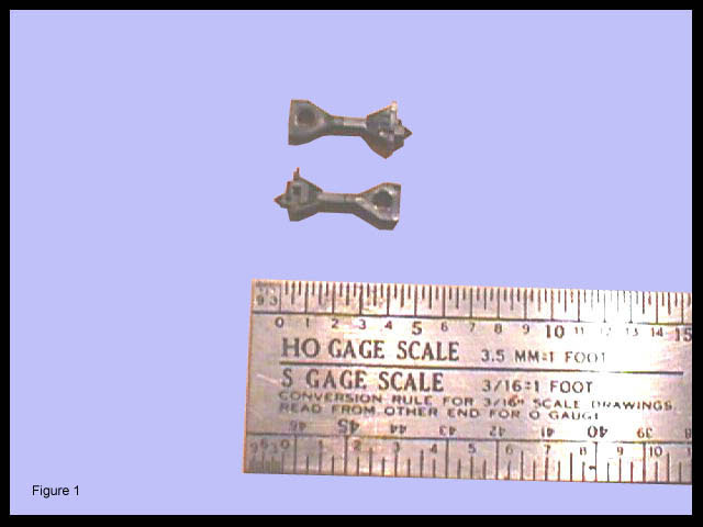
1. The second
step will be to remove the base of the coupler leaving only
the shank. This is accomplished by cutting the coupler parallel
to the mid point of the coupler mounting hole as shown in figure
1 and then filing the shank down to the size that will
slide snugly into a piece of Plastruct STFS-4 .125" square
tubing or Evergreen Scale Models StripStyrene Item No.
252 (Walthers #269-0252).
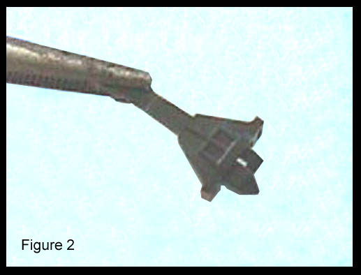
2. The next step is to
prepare the drawbar to receive the coupler. Notice that the coupler
face has nothing to do with maintaining the coupling of the cars.
There is an "L" shaped bar under the coupler that
mates with the identical bar on the mating coupler and that is
what holds the cars together. We will call this part the coupler
connector. To operate successfully, the coupler connector is
mounted on a split shaft separate from the coupler head. This
split shaft allows sufficient freedom vertically for this coupler
connector to operate. To maintain this freedom in the new drawbar,
a small notch is cut into the base of the drawbar as shown in
figure 2.
3. The coupler is then
inserted in the prepared end of the tubing in a manner that the
coupler connector shank fits just beneath the notched end. If
inserted correctly, the coupler connector should have sufficient
room for vertical movement to uncouple without breakage. Once
the coupler fit is made and a snug fit of the entire coupler shank
can be made inside the square tube of the drawbar. Remove, and
apply ACC and re-attach inside the coupler drawbar
4. Two more actions must
take place before mounting the coupler to the car body.
a. Obtain some Plastruct MS-60 solid bar
stock, .060" by .060", or Evergreen Scale Models Item
No. 153 (Walthers 269-0153) and place inside the coupler drawbar
from the one remaining open end. When you have inserted the bar
stock as far as it will go, then remove and apply generous amounts
of Plastruct Cement and reinsert. When the glue is thoroughly
set, cut flush with the end of the drawbar.
b. As an optional method of ensuring against
pulling the coupler from the modified drawbar, using a #67 drill,
drill a hole through the side of the drawbar, through the coupler
shank and out the outer side of the drawbar. Then insert a piece
of .019 wire, secure with ACC and cut flush on both sides.
5. In attaching to the
car body, more than likely you will have a coupler mounting hole
already provided. If you are fortunate to have a local source
of prototype data or better yet, a nearby museum where prototype
dimensions can be readily obtained, you may use such data as a
source of information.
a. We found that on a prototype PERy 400
series "Blimp", the length of the drawbar from the center
pin of the draft gear to the striking face of the coupler is 51.75"
and the face of the coupler is between 12.75 and 16.25 inches
from the buffer depending upon the buffer block type. The center
of the coupler is 30.5" from the top of the railhead.
b. We also were fortunate to know that the
distance from the coupler striking face to the center pin on
a Hollywood Car was 72" and the coupler face is 15 inches
from the anti-climber. The center of the coupler is 18"
from the top of the rail head. Please refer to the matrix below
for some typical prototype dimensions provided for your modeling
information.
| WESTINGHOUSE COUPLERS - PACIFIC ELECTRIC CARS | ||||||
| CARS/CLASS | COUPLER TYPE | CENTER PIN - DRAFT GEAR | STRIKING FACE TO BUFFER | CENTER OF COUPLER HEAD TO RAILTOP | REMARKS | |
| TO STRIKING FACE | TO CENTER OF CIRCLE IRON | |||||
| 446-447 | C-3 | 60.0 INCHES | 40.0 INCHES | 28.0 INCHES | ||
| 448 | C-3 | 60.0 INCHES | 40.0 INCHES | 28.0 INCHES | ||
| 450-465 | C-3 | 60.0 INCHES | 40.0 INCHES | 28.0 INCHES | ||
| 600-759* | K-1-A | 72.0 INCHES | 54.0 INCHES | 15.0 INCHES | 18.0 INCHES | |
| 5000-5029 | K-1-A | 18.0 INCHES | 18.875 INCHES | |||
| 1100-1149 | H-2-A | |||||
| 1200-1251 | H-2-A | 52.0 INCHES | 28.625 INCHES | 9.0 INCHES | 34.0 INCHES | |
| 1252-1263 | H-2-A | 53.0 INCHES | 9.0 INCHES | 34.0 INCHES | ||
| 1299 | H-2-A | 53.0 INCHES | 9.0 INCHES | 34.0 INCHES | ||
| 300-318 | H-2-A | 51.75 INCHES | 26.5 INCHES | 13.75 INCHES | 30.5 INCHES | |
| 400-437; 450-459 | H-2-A | 51.75 INCHES | 26.5 INCHES | 12.75 & 16.25 INCHES | 30.5 INCHES | STRIKING FACE TO BUFFER DIMENSION VARIES ACCORDING TO TYPE BUFFER USED |
| 496-499 | H-2-A | 51.75 INCHES | 26.5 INCHES | 15.0 & 16.25 INCHES | 30.5 INCHES | 15" AT BAGGAGE END; 16.25" AT VESTIBULE END |
| *ALSO LATER 5050 CLASS | All data provided by Dave Garcia, Orange Empire Railway Museum | |||||
c. As a general rule, the radius of the
coupler swing was usually concentric with the radius of the anti-climber
or buffer, especially on street cars and interurbans where city
curves had to be traversed. Models often do not adhere to this
fact as mounting the coupler in that position would usually impede
the swing of the power truck.
6. Once you decide the
proper place to drill the mounting hole in the drawbar, drill
a perfectly vertical hole in the drawbar with the same #67 drill
and then finish with a #55 drill. Normally, we use 0-80 hex screws
with one 0-80 washer to attach the drawbar to the car. In some
cases, we have had to tap the existing mounting boss to ensure
a correct fit. Since our first applications of these "H-1"
couplers were on HO scale Suydam #400 PERy "Blimp" coaches,
Suydam #498 "Blimp" combines, and Suydam PERy steel
coaches and combines of the 1200 and 1300 series, all of our experience
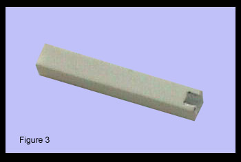
has been limited to these cars. On some of the early imported
"Blimps", no mounting boss was provided so we made
our own coupler center pin mount from solid .125" styrene
using the prototype dimensions for positioning the center pin
on the model. The bar is mounted perpendicular to the center
of the model between the steps, as shown in figure
3. The bar is drilled with a #55 drill and along
with the brass beneath it and then tapped for 0-80 screw. An
0-80 washer is placed between the fashioned drawbar and the car
body. I have affixed the bar stock with both screws and ACC and
have had no problems with either method.
7. The amount of play
that you want in the drawbar depends mainly on the type of track
upon which you will be operating, but, the SCTC has found that
the combination of #55 drill, 0-80 screw and 0-80 washer seems
to provide sufficient play for uneven track.
8. When we started this
article with the second step, you may have thought that to be
a typographical error. It was not. The first step is
to acquire these couplers in the United States. The Kato part
number is 1-410-C3. It is normally only marketed with the
Japanese prototype multiple unit cars. Efforts to try and get
U.S. distributors to handle these couplers so far have not been
successful. However, as of March 1998, Custom Traxx, P.O. Box
641175, West Los Angeles, CA 90064-1175 has obtained a limited
supply at $5.00/pair. Refer to the KH coupler when ordering.
PROCEDURE FOR INSTALLING THE Kato "H-2"
COUPLER - METHOD TWO
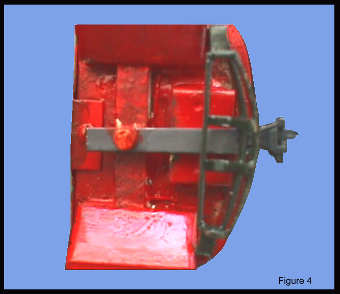
1. Again, the
second step will be to remove the base of the coupler leaving
only the shank. This is accomplished by cutting the coupler at
the base of the triangular mounting hole area as shown in figure
4 and then filing the shank down to the size that will
slide snugly into a piece of K&S 3/32" square
brass tubing (Walthers #370-0150).
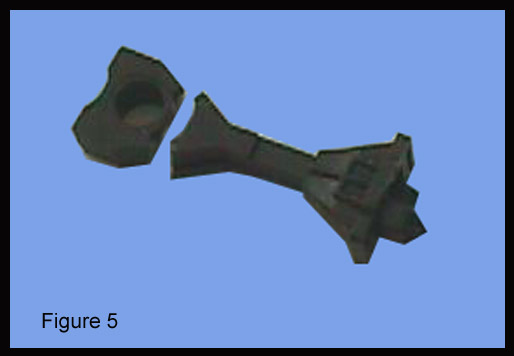
2. The next step is to
prepare the drawbar to receive the coupler. To operate successfully,
the coupler connector is mounted on a split shaft which allows
sufficient freedom vertically for this coupler connector to operate.
To maintain this freedom in the new drawbar, a small notch is
filed into the base of the brass drawbar as shown in figure
5.
3. The coupler is then
inserted in the prepared end of the tubing in a manner that the
coupler connector shank fits just beneath the notched end. If
inserted correctly, the coupler connector shank should have sufficient
room for vertical movement to uncouple without breakage. Once
the coupler fit is made and a snug fit of the entire coupler shank
can be made inside the square tube of the drawbar, remove the
coupler and place aside as we will be soldering to the drawbar
and prefer not to melt the coupler during this step (The author
has a melted coupler to prove it).
4. In attaching
to the car body, more than likely you will have a coupler mounting
hole already provided. If you are fortunate to have a local source
of prototype data or better yet, a nearby museum where prototype
dimensions can be readily obtained, you may use such data as a
source of information.
a. We located a prototype at the Orange Empire
Railway Museum and found that the distance from the coupler face
to the center pin on a Hollywood Car was 72"; the distance
from the center pin to the radius mounting bar was 54"; and
the coupler face was 15 inches from the face of the anti-climber.
Also it is important to know that for these cars the center of
the coupler was only 18 inches from the top of the railhead, almost
half the distance required for steam road AAR couplers.
The Suydam models do not follow these dimensions in this
area, as the mounting screw (center pin) is only about 48"
from the face of the anti-climber.
b. As mentioned earlier in this article,
the radius of the coupler swing was usually concentric with the
radius of the anti-climber or buffer, especially on street cars
and interurbans where city curves had to be traversed. The best
operation is obtained when any radial coupler is mounted in that
manner.
6. On most of the imported
HO scale "Hollywood" cars there is provided a mounting
screw through a "U" shaped plate fashioned plate
which can be used to maintain the coupler level and prevent it
from dragging onto the track. This is crucial to effective operation
as there must be sufficient vertical movement to avoid derailments
while the coupler is only a foot and a half from the top of the
rail head or the blacktop.
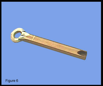
a. To mount the coupler to the body, we first
decided the length of the drawbar. To ensure that the coupler
clears the buffer throughout the entire radial swing, we discovered
that the drawbar should be 36 scale inches long. You may make
your own conclusions using the provided mount on other cars, or
you can fashion your own mount using a 2-56 screw on the prototypical
location. Using the stock brass bar, cut a horizontal notch 3/64"
long in one end. This notch should be placed in the upper one-third
of the brass tubing and should be angled slightly as shown in
Figure 6.
b. Solder
a brass 2-56 washer into the notch. The angled notch will enable
the washer to maintain the coupler in a level state.
c. File the hole in the washer to clear the
mounting screw provided. Do not overfile here. This is a careful
file and fit maneuver until the mounting screw can pass through
the modified 2-56 washer.
d. Attach the coupler into the opposite end
of the drawbar with ACC. (We recommend CA4000 which is available
from Dental Ventures of America, Corona, CA (909) 228-0606. They
have what we feel is the best ACC applicator on the market.)
e. Mount the drawbar and ensure that the
fit is correct
7. The amount of play
that you want in the drawbar depends mainly on the type of track
upon which you will be operating, but, the SCTC has found that
this method with slight adjustments of the U-shaped mounting plate
provided on these cars worked for us.
8. Again, the first
step is to acquire these couplers in the United States. However,
as of March 1998, Custom Traxx, P.O. Box 641175, West Los Angeles,
CA 90064-1175 has obtained a limited supply at $5.00/pair. Refer
to the KH coupler when ordering.
ABOUT THE AUTHORS
The Southern California Traction Club (SCTC) was
founded in October 1995 by six avid electric railway enthusiasts;
George Huckaby, West Los Angeles; CA; Fred Burg, Downey, CA, Charles
Hepperle, Torrance; Bob Hill, Lakewood; CA; Fred Hutchins, Venice,
CA; and Bill Kift, Long Beach, CA. At the time of the writing
of this article, the club had added the following members; Byron
Brainard, Laguna, CA, Mike DeGhetto, West Los Angeles, Dave Garcia,
Downey; CA, George Jones, Culver City, Toshisuke Matsumoto, Tokyo,
Japan; and Janik Podganski, Hawthorne, CA.
The club models electric railways in HO scale using
both the modular approach and functional overhead wires. The
cars actually receive their power from those overhead wires.
All modules are based on the physical standards of the East Penn
Traction Club while using a slightly modified electrical system.
Although the majority of the cars operated are of Pacific Electric
Railway prototype, vehicles of other operators, such as Los Angeles
Railway (LARy), Los Angeles Transit Lines (LATL), Philadelphia
Rapid Transit (PRT) Philadelphia Transportation Company (PTC)
and Sacramento Northern Railway (SNRy) are often operated. Any
HO scale electric railway vehicle that uses a trolley pole to
collect current can be operated on the SCTC modules, subject to
a few qualifications.
For more about the authors themselves, refer to
the article on Pacific Electric paint schemes which is also in
the Trolleyville Schoolhouse at www.trolleyville.com.
CONCLUSION
Any article placed on
Trolleyville is so placed to promote the model electric railway
hobby and to aid those modelers who desire to model electric railways
and can not seem to find the information or supplies that they
need. These methods are not ultimate ends in themselves and some
readers may find and already know simpler and even better ways
to accomplish these tasks. All we ask that if you find an error
in our presentation or know a better way, why not share it with
us and the rest of the hobby. We choose not to respond to those
who criticize and have no alternate workable suggestions.
end
[an error occurred while processing this directive]